

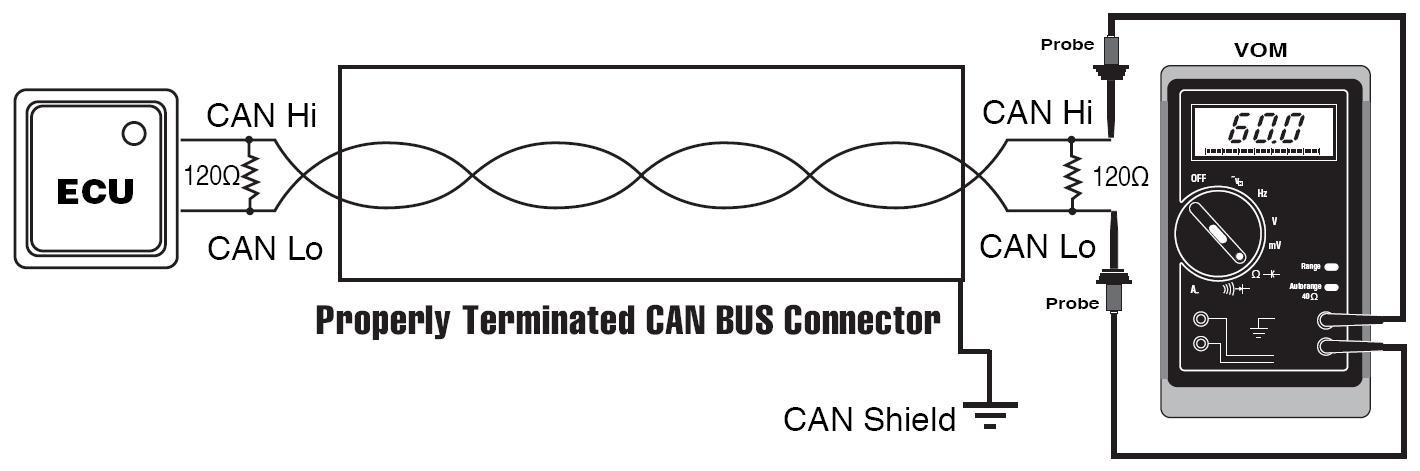
Line Resistance (Between CAN High and CAN Low) should read 60 ohms.
 |  |  |
Products:
IM-1 Inertial Measurement Device
SG-1-C Strain Gage Amplifier to CAN
LINC Smartphone and Tablet Bridge
11148 Treynorth Drive
Suite A
Cornelius, NC 28031
(704) 769-0001
Maximize Your Metrics with Techmor's Measurement Toolsre

Contact Us
Precision metrics measurement is a critical aspect of many industries, particularly in the automotive sector where accuracy and consistency are essential to ensure quality and safety. From engine performance to vehicle emissions, precise measurements are crucial for meeting regulatory requirements, improving efficiency, and enhancing the overall driving experience.
One of the most significant challenges in precision metrics measurement is achieving the level of accuracy required for reliable results. This requires careful calibration of measurement instruments, as well as attention to environmental factors such as temperature and humidity that can affect the accuracy of measurements. In addition, data analysis and interpretation play a critical role in determining the relevance and usefulness of measurement data.
Automotive applications of precision metrics measurement include everything from engine testing to fuel efficiency analysis, emissions testing, and more. Advances in technology have enabled more precise and efficient measurement techniques, such as the use of laser-based sensors and automated testing systems that can perform measurements quickly and accurately.
One of the most promising areas of development in precision metrics measurement for automotive applications is the use of artificial intelligence (AI) and machine learning (ML) to automate data analysis and interpretation. By using algorithms to analyze large amounts of measurement data, AI and ML can provide valuable insights into vehicle performance, identify areas for improvement, and help automotive manufacturers develop more efficient and reliable products.
Overall, precision metrics measurement and its applications in the automotive industry are critical for ensuring quality, safety, and efficiency. Advances in technology and the use of AI and ML are likely to play an increasingly important role in the future of precision measurement and automotive development.
Copyright 2024 Techmor Inc.